Quantcast
Channel: RGB LED – Hackaday
Viewing all 172 articles
Browse latest View live

A Raspi Ambilight With HDMI Input

$
0
0

FPZXID5HTEFMWFR.LARGE

With the Raspberry Pi now most famously known as a $30 media PC, it only makes sense that the best uses for the GPIO pins on the Pi are used for an Ambilight. [Great Scott Labs] put up a great video on using the Pi as a uniquely configurable Ambilight with Hyperion and just about any video input imaginable.

This isn’t the first Ambilight clone [Great Scott] has put together, but for the first version the Ambilight functioned only under Raspbian and not any random HDMI input. The new version solves this by using an HDMI splitter box, feeding into an HDMI to composite converter, and finally into a USB composite capture dongle attached to the Raspi.

With the software in the instructions, the Raspi effectively mirrors the video coming from the video capture dongle. The Pi is running Hyperion to control a strip of WS2801 RGB LEDs, making the back of any TV glowey and blinkey.

Since [Great Scott] is using a component video signal as an input, the adapters necessary to have any device work with this Ambilight are readily available. We’d honestly like to see this build working with the old Commodore disk access screen border going nuts, so be sure to send that in if you ever get that working.


Filed under: led hacks, Raspberry Pi

Driving 1000 NeoPixels With 1k Of Arduino RAM

$
0
0

timing

NeoPixels, or WS2812 RGB LEDs, are the display device du jour for impressive and blinding lighting projects. Commonly known for very tight timing requirements, [Josh] discovered this is, in fact, usually unnecessary. The timing requirements for NeoPixels aren’t as bad as they seem, once you get to know them.

The official WS2812 timing specs give values that are fairly constraining for anyone writing a library to drive these RGB LED pixels, but simplifying the timing diagram by assuming a 50% duty cycle on the data lines and ignoring the longer maximum times results in a surprising conclusion: the only tight timing parameter for NeoPixel signaling is the maximum width of the 0-bit pulse.

Realizing this, [Josh] wrote a simple demo program to drive over 1000 NeoPixels – an 11 meter long strip – using 1K of RAM on an Arduino. The trick comes by simply delaying the bitbanging a set number of cycles. No obtuse assembly required.

There is only one problem with [Josh]‘s method of driving a nearly unlimited amount of NeoPixels – building a display where every NeoPixel is an element in a larger image, such as in a video display, is impossible on systems with limited amounts of RAM. The code writes values to the NeoPixel strip algorithmically, so if you can’t build your animation with for loops, you’re out of luck. Still, Driving this many NeoPixels is a migraine trigger, and we have to give [Josh] credit for doing this with 1K of RAM.

Check out the video of [Josh]‘s extreme NeoPixel strip below.


Filed under: Arduino Hacks, led hacks

Koch Lamp is 3D Printed with a Twist

$
0
0

Koch Lamp

[repkid] didn’t set out to build a lamp, but that’s what he ended up with, and what a lamp he built. If the above-pictured shapes look familiar, it’s because you can’t visit Thingiverse without tripping over one of several designs, all based on a fractal better known as the Koch snowflake. Typically, however, these models are intended as vases, but [repkid] saw an opportunity to bring a couple of them together as a housing for his lighting fixture.

Tinkering with an old IKEA dioder wasn’t enough of a challenge, so [repkid] fired up his 3D printer and churned out three smaller Koch vases to serve as “bulbs” for the lamp. Inside, he affixed each LED strip to a laser-cut acrylic housing with clear tape. The three bulbs attach around a wooden base, which also holds a larger, central Koch print at its center. The base also contains a PICAXE 14M2 controller to run the dioder while collecting input from an attached wireless receiver. The final component is a custom control box—comprised of both 3D-printed and laser-cut parts—to provide a 3-dial remote. A simple spin communicates the red, green, and blue values through another PICAXE controller to the transmitter. Swing by his site for a detailed build log and an assortment of progress pictures.


Filed under: 3d Printer hacks, led hacks, Microcontrollers

The Megascroller, For Video Games In The Round

$
0
0

megascroller

The folks at NYC Resistor have a thing for circular displays, it seems. Their earlier Hexascroller was a ceiling mounted display with six 30×7 displays – good enough to display the time and a few textual message in six directions. The Octoscroller bumped up the display capability with eight 16×32 RGB LED panels. Now the Megascroller, a 32-sided 512×64 display is hanging in the hackerspace, complete with 360° Mario and Pong.

The Megascroller is one of [Trammell Hudson]‘s projects, constructed out of sixty-four 32×16 RGB LED matrices. That’s an impressive amount of controllable LEDs, that required a lot of processing power: namely, the BeagleBone-powered LEDscape board used in their earlier Octoscroller

As far as applications go, they naturally have Pong, but a more interesting application is the side-scrolling Mario that requires you to move around the display as you play. You can check out a video of that below.

If you’d like to see the Megascroller in person, as well as a whole bunch of other crazy blinking interactive projects, NYC Resistor is holding a an interactive show this weekend, beer provided.


Filed under: led hacks

The 200 LED Ring Clock

$
0
0

clock-ws2812

There are LED clocks, and then there are LED clocks that can blind you from 30 paces. [Stiggalicious's] LED ring clock is of the latter variety. 200 WS2812B/Neopixel RGB LEDs drive the ring clock to pupil searing levels. The clock runs on ATMega1284P, with timekeeping handled by an NXP PCF8563 real-time clock chip. Code is written in Arduino’s wiring language using Adafruit’s Neopixel library.

Building the clock with a single Printed Circuit Board (PCB) would be both expensive and wasteful. [Stiggalicious] cleverly designed his clock to be built with 8 copies of the same PCB. Each board makes up a 45° pie slice of the ring. All 8 PCBs have footprints for the CPU, clock chip, and other various discrete parts, but only the “master” section has these parts populated. 7 “slave” sections simply pass clock, data, power and ground through each LED. He used Seeedstudio’s board service to get 10 copies of his PCB made, just in case there were any mistakes.

[Stiggalicious] rolled the dice by buying exactly the 200 LEDs he needed. Either he got really lucky, or the WS2812 quality testing has improved, because only one LED had a dead blue LED.

If you’d like to find out more, [Stiggalicious] gives plenty of details in his Reddit thread. He doesn’t have a webpage setup for the clock but he’s uploaded his source code (pastebin link) and Altium schematic/PCB files (mega.nz link). We may be a bit biased, but hackaday.io would be a perfect spot for this or any other project!


Filed under: clock hacks, led hacks

Here Come the RGB LED Clones

$
0
0

ws2812 and clones timing

It seems like every third project on Hackaday uses WS2812 RGB LEDs in some way. We all love our blinkenlights, and bright, cheap, serial controlled RGB LEDs are the bees knees.

As with all products these days, competing manufacturers have discovered the huge market for these things, and clones are now available. [Tim] recently took a look at the PD9823, as well as three versions of the WS2812. [Tim] is considered something of a WS2812 guru here at Hackaday. You might remember him from his WS2812 driver optimization article, which should be required reading for any WS2812 hacker.

As many of us know, the timing characteristics for these LEDs can be a pain to work with. The values also differ between the WS2812S and WS2812B. [Tim] discovered that the new through hole WS2812D parts are different yet again, though rather close to the B parts. The PD9823′s designers must have studied the WS2812′s closely, as their 190ns time base falls directly between WS2812S 166ns time and the 208ns time of the WS2812B. The PD9823 also requires a slightly longer reset pulse.

The takeaway is that well written drivers such as [Tim's] should have no problem with the new parts, but compatibility is something to keep in mind as more clones hit the market.


Filed under: led hacks

DIY 3D Tilt Sensor

$
0
0

tilt 
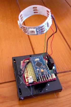
If you’re trying to detect the orientation of an object, sometimes you really don’t need a 6DOF gyro and accelerometer. Hell, if you only need to detect if an object is tilted, you can get a simple “ball in a tube” tilt sensor for pennies. [tamberg] liked this idea, but he required a tilt sensor that works in the X, Y, and Z axes. Expanding on the ‘ball in a tube’ construction of simple tilt sensors, he designed a laser cut 3D tilt sensor that does all the work of of a $30 IMU.

The basic design of this tilt sensor is pretty simple – just an octahedron with four nails serving as switch contacts at each vertex. An aluminum ball knocks around inside this contraption, closing the nail head switches depending on what orientation it’s in. Simple, and the three dimensional version of a ball in tube tilt sensor.

To get the tilt data to the outside world, [tamberg] is using an Adafruit Bluetooth module, with two of the nails in each corner connected to a pin. With just a little bit of code, this 3D tilt sensor becomes a six-way switch to control an RGB LED. Video of that below.


Filed under: cnc hacks

PIC Up a NeoPixel Ring and C What You Can Do Using This Tutorial

$
0
0

lit ringAs [Shahriar] points out in the introductory matter to his latest video at The Signal Path, Arduinos are a great way for a beginner to dig into all kinds of electronic excitement, but they do so at the cost of isolating that beginner from the nitty gritty of microcontrollers. Here, [Shahriar] gives a very thorough walkthrough of a 60-neopixel ring starting with the guts and glory of a single RGB LED. He then shows how that ring can easily be programmed using a PIC and some C.

[Shahriar]‘s eval board is a simple setup that he’s used for other projects. It’s based on the PIC18F4550 which he’s programming with an ICD-U64. The PIC is powered through USB, but he’s using a separate switching supply to power the ring itself since he would need ~60mA per RGB to make them burn white at full brightness.

He’s written a simple header file that pulls in the 18F4550 library, sets the fuses, and defines some constants specific to the ring size. As he explains in the video, the PIC can create a 48MHz internal clock from a 20Mhz crystal and he sets up this delay in the header as well. The main code deals with waveform generation, and [Shahriar] does a great job explaining how this is handled with a single pin. Before he lights up the ring, he puts his scope on the assigned GPIO pin to show that although the datasheet is wrong about the un-delayed width of the low period for a zero bit, it still works to program the LEDs.

[Shahriar] has the code available on his site. He is also holding a giveaway open to US residents: simply comment on his blog post or on the video at YouTube and you could win either a TPI Scope Plus 440 with probes and a manual or a Tektronix TDS2232 with GPIB. He’ll even pay the shipping.


Filed under: led hacks, Microcontrollers

Teaching the Word Clock Some New Tricks

$
0
0

wordclock2014

[Joakim] has built a clock that spells out the time in words. Wait a second – word clock, what is this, 2009? Word clocks are one of those projects that have become timeless. When we see a build that stands out, we make sure to write it up. [Joakim's] clock is special for a number of reasons. The time is spelled out in Norwegian, and since the clock is a birthday gift for [Daniel], [Joakim] added the his full name to the clock’s repertoire.

One of the hard parts of word clock design is controlling light spill. [Joakim] used a simple 3D printed frame to box each LED in. This keeps the spill under control and makes everything easier to read. The RGB LED’s [Joakim] used are also a bit different from the norm. Rather than the WS2812 Neopixel, [Joakim] used LPD8806 LED strips. On the controller side [Joakim] may have gone a bit overboard in his choice of an Arduino Yun, but he does put the ATmega328 and Embedded Linux machine to good use.

The real magic happens at boot. [Daniel's] name lights up in red, with various letters going green as each step completes. A green ‘D’ indicates an IP address was obtained from the router’s DHCP server. ‘N’ switches to green when four NTP servers have been contacted, and the Linux processor is reasonably sure it has the correct time. The last letter to change will be the ‘E’, which reports ambient light.

[Joakim] added a web interface to trigger his new features, such as a rainbow color palette, or the ability to show minutes by changing the color of the letters K,L,O,K. The final result is a slick package, which definitely brings a 2009 era design up to 2014 standards!


Filed under: Arduino Hacks, clock hacks

Infinity Mirror Clock: There’s a Time Joke There Somewhere

$
0
0

Infinity Mirror Clock

We don’t think we’ve seen an Infinity Mirror Clock before, but we love this new twist on an old favorite. Different colors distinguish between seconds, minutes and hours, and an additional IR sensor detects when someone is directly in front of the clock and switches the LEDs off, allowing it to be used as a normal mirror. This build is the work of [Dushyant Ahuja], who is no stranger to hacking together clocks out of LEDs. You can tell how much progress he’s made with the mirror clock by taking a glance at his first project, which is an impressive creation held together by jumbles of wire and some glue.

[Dushyant] has stepped up his game for his new clock, attaching an LED strip along the inside of a circular frame to fashion the infinity mirror effect. The lights receive a signal from an attached homemade Arduino board, which is also connected to a real-time clock (RTC) module to keep time and to a Bluetooth module, which allows [Dushyant] to program the clock wirelessly rather than having to drag out some cords if the clock ever needs an adjustment.

Stick around after the jump for a quick demonstration video. The lights are dazzling to watch; [Dushyant] inserted a stainless steel plate at the center of the circle to reflect the outer rim of LEDs. After a quick rainbow effect, it looks like the mirror enters clock mode. See if you can figure out what time it is. For a more step-by-step overview of this project, swing by his Instructables page.


Filed under: Arduino Hacks, clock hacks, led hacks

Voice Controlled RGB LED Lamp

$
0
0

Voice Controlled Lamp

[Saurabh] wanted a quick project to demonstrate how easy it can be to build devices that are voice controlled. His latest Instructable does just that using an Arduino and Visual Basic .Net.

[Saurabh] decided to build a voice controlled lamp. He knew he wanted it to change colors as well as be energy-efficient. It also had to be easy to control. The obvious choice was to use an RGB LED. The LED on its own wouldn’t be very interesting. He needed something to diffuse the light, like a lampshade. [Saurabh] decided to start with an empty glass jar. He filled the jar with gel wax, which provides a nice surface to diffuse the light.

The RGB LED was mounted underneath the jar’s screw-on cover. [Saurabh] soldered a 220 ohm current limiting resistor to each of the three anodes of the LED. A hole was drilled in the cap so he’d have a place to run the wires. The LED was then hooked up to an Arduino Leonardo.

The Arduino sketch has several built-in functions to set all of the colors, and also fade. [Saurabh] then wrote a control interface using Visual Basic .Net. The interface allows you to directly manipulate the lamp, but it also has built-in voice recognition functionality. This allows [Saurabh] to use his voice to change the color of the lamp, turn it off, or initiate a fading routing. You can watch a video demonstration of the voice controls below.


Filed under: Arduino Hacks, led hacks

Mood Lighting with LEDs and an Arduino

$
0
0

arduino ir candle

Regular candles can be awfully boring at times. They can only produce one color and the flicker is so… predictable. They can’t even be controlled by an infrared remote control, not to mention the obvious fire hazard. Now, however, [Jose] has come up with an LED candle that solves all of these problems. (Original link to the project in Spanish.)

The heart of the project is an Arduino Pro Mini, which is especially suited for this project because of its size. [Jose] put the small form-factor microcontroller in the base of a homemade wax enclosure and wired it to a Neopixel WS2812b LED strip. The strip can produce any color, and has some programmed patterns including flicker, fade, rainbow, and fire.

The artificial candle is controlled with an infrared remote control, and all of the code for the project is available on the project site if you want to build your own. [Jose] has been featured here before for his innovative Arduino-driven RGB lighting projects, and this is another great project which builds on that theme!


Filed under: Arduino Hacks

iPhone-Controlled Daft Punk Helmet

$
0
0

A few years ago, [Marc] had access to a really big, very expensive 3D printer. Daft Punk helmets were – and still are – extremely cool builds, so with a bit of modeling, [Marc] and his friend [Alex] put together a model and printed out a Daft Punk [Thomas] helmet with the intention of turning it into the keystone of a great costume. A few things got in the way, and the [Thomas] helmet was left on a shelf for a few years. Fast forward to a few months ago and [Marc] took up the project again. The result is a 3D printed Daft Punk helmet loaded up with 320 WS2811 LEDs.

The 3D printed helmet was modeled well and printed in polycarbonate, but with any extrusion-based printer, there will be ridges and layers to sand, fill, prime and paint. This task was delegated to another friend, [Shaggy], while [Marc] got busy on the electronics.

The LEDs for the visor and ‘earmuffs’ are WS2811 LEDs, but not the SMD versions we’re so used to seeing. These are 8mm through-hole LEDs mounted in a lasercut piece of acrylic. Control of the LEDs is done with a Teensy 3.1 with [Paul Stoffregen]‘s OctoWS2811 library. With the matrix wired up, batteries installed, WiFi capability added, and the helmet painted (not chromed; that will probably happen later, though), [Marc] had a copy of the [Thomas] helmet controllable through an iPhone.

If you’d like to check out more of [Marc]‘s work, we posted something on his RGB LED suit and pneumatic Star Trek doors a few years ago.

Video below.


Filed under: wearable hacks

A Wooden LED Matrix Coffee Table

$
0
0

[johannes] writes in with a pretty impressive LED table he built. The table is based around WS2801 serially addressable LEDs which are controlled by a Raspberry Pi. The Pi serves up a node.js-driven web interface developed by [Andrew Munsell] for a room lighting setup. The web interface controls the pattern shown on the display and the animation speed.

[johannes] built a wooden coffee table around the LED matrix, which includes a matte glass top to help diffuse the lighting. An outlet to plug in a laptop and two USB charging ports are panel-mounted on the side of the enclosure, which are a nice touch. The power supply for the LEDs is also inside the enclosure, eliminating the need for an external power brick.

While [johannes] hasn’t written any software of his own yet, he plans on adding music synchronization and visualizations for weather and other data. Check out the video after the break to see the table in action.


Filed under: home hacks

Digging into the APA102 Serial LED Protocol

$
0
0

[Tim] got his hands on some APA102 RGB LEDs, which are similar in function to the common WS2812 addressable LEDs seen in many projects we’ve featured. The advantage of APA102 LEDs is that they don’t have the strict timing requirements of the WS2812. These LEDs are controlled with a SPI bus that can be clocked at any arbitrary rate, making them easy to use with pretty much any microcontroller or embedded system.

After working with the LEDs, [Tim] discovered that the LEDs function a bit differently than the datasheet led him to believe. [Tim] controlled a strand of APA102 LEDs with an ATtiny85 and connected a logic analyzer between some of the LEDs. He discovered that the clock signal of the SPI interface isn’t just passed through each LED, it actually looks like it’s inverted on the output. After some investigation, [Tim] found that the clock signal is delayed by a half period (which looks like an inversion) before it’s passed to the next LED. This gives the next LED in the strand enough time for data on the data line to become valid before latching it in.

Since the clock is delayed, [Tim] discovered that additional bits must be clocked as an “end frame” to generate clock signals which propagate the remaining data to the end of the strand. Although the datasheet specifies a 32-bit end frame, this only works for strings of up to 64 LEDs. More bits must be added to the end frame for longer strands, which the datasheet doesn’t even mention. Check out [Tim]’s post for more information, where he walks you through his logic analysis of the APA102 LEDs.


Filed under: led hacks

The Epoch Christmas Tree

$
0
0

It’s that time of the year again, and the halls are being decked with trees, the trees covered in lights, and everyone working in retail is slowly going insane from Christmas songs piped over the PA. [Dan] has a tree and a bunch of programmable LEDs, but merely pumping jollity down that strip of LEDs wouldn’t be enough. The Nerd Quotient must be raised even higher with a tree that displays a Unix timestamp.

This build was inspired by an earlier, non-tree-based build that displays Unix time on a 32 LED array. That build used an ATMega328p for toggling LEDs on and off. This time around, [Dan] is using a dedicated LED controller – the AllPixel – that just wrapped up a very successful Kickstarter campaign. The AllPixel is, in turn, controlled by a Raspberry Pi running the BiblioPixel library,

The tree displays the current time stamp in binary across 32 spaces, with green representing a ‘one’ and a red representing ‘zero’. The top of the tree is the least significant bit, but in case [Dan] gets tired of the bottom of the tree staying completely still for the rest of this holiday season, he can switch the order making the base of the tree the LSB.

Video below.


Filed under: Holiday Hacks, led hacks

FPGA Ambilight Clone Packs a Ton of Features

$
0
0

[Stephen] designed a standalone Ambilight clone built around an FPGA and recently added many new features to make his design even better. His original design was based around a Spartan 3-E FPGA, but his new design uses the Papilio One board with a Spartan-6 LX9 FPGA. This gives him dedicated DSP hardware and more RAM, allowing him to add more processing-intensive features.

[Steven]’s new board can drive up to 4096 LEDs total, and each LED is colored from one of 256 segmented screen areas. The output of the LEDs is smoothed over a configurable time period which makes the result a bit more pleasant. [Steven] also added color correction matrices and gamma correction tables to make up for differences in LED coloration and so the output can be fine-tuned to the color of the wall behind the TV.

Finally, [Steven] added multiple configurations which can be stored in Flash memory. The FPGA can detect letterboxes and pillarboxes in the video stream and change to a corresponding configuration automatically, so settings rarely need to be manually adjusted. He also added an extensive serial interface to configure all of the parameters and configurations in Flash. Be sure to check out the video after the break to see his setup in action.


Filed under: led hacks

RGB Bike Rim Lights

$
0
0

[Yvo] sent us his latest creation, this awesome POV RGB bicycle rim light build, which features a circular interweaving of common RGB LEDs that face outward along the rim as they display constantly changing animations based on the wheel’s rpm.

Like many POV wheel builds, [Yvo]’s takes advantage of a hall effect sensor and stationary magnet to determine how fast the wheels are spinning. Unlike most POV builds, however, [Yvo’s] creation doesn’t have just one or two RGB sticks clamped onto a spoke. Instead, his wheels boast several individual RGB LED modules mounted along the rim.

Each wheel has six modules, and each module contains a scratch-build LED controller (a daisy chain of 74HC595 shift registers) that fits into a custom-made 3D-printed enclosure. The enclosures mounts onto some aluminum strips along with the RGB LEDs, and the aluminum strips mount to the wheels by straddling the rim.

At speed, the lights go into POV mode to simulate headlights / brakes with white in the front and red in the back. Check out the difference these custom circular modules make when riding and when at rest in a video below.


Filed under: led hacks, transportation hacks

RGB LED Matrices With The STM32 and DMA

$
0
0

A few years ago, [Frans-Willem] bought a few RGB LED panels. Ten 32×16 panels is a lot of LEDs, and to drive all of these panels requires some sufficiently powerful hardware. He tried working with an FPGA development board, but that didn’t have enough memory for 24-bit color. The microcontroller du jour – a TI Stellaris – couldn’t get more than 16 bits of color without flickering. With a bunch of LEDs but no way to drive them, [Frans-Willem] put the panels in a box somewhere, waiting for the day they could be used to their fullest capacity.

This day came when [Frans-Willem] was introduced to the STM32 series of chips with the F1 Discovery board. While looking for some electronic playthings to use with this board, he stumbled upon the LED panels and gave them one more try. The results are spectacular, with 33 bits of color, with animations streamed over a router over WiFi.

The panels in question are HUB75 LED panels. In the 32×8 panels, there are six data pins – two each for each color – four row select pins, and three control pins. The row select pins select which row of pixels is active at any one time. Cycle through them fast enough, and it will seem like they’re all on at once. The control pins work pretty much like the control pins of a shift register, with the data pins filling in the obvious role.

The code that actually drives the LEDs all happens on an STM32F4 with the help of DMA and FSMC, or the Flexible Static Memory Controller found on the chip. This peripheral takes care of the control lines found in memory, so when you toggle the write strobe the chip will dump whatever is on the data lines to a specific address in memory. It’s a great way to take care of generating a clock signal.

For sending pixels to this display driver, [Frans-Willem] is using the ever-popular TP-Link WR703N. He had originally planned to send all the pixel data over the USB port, but there was too much overhead, a USB 1.1 isn’t fast enough. That was fixed by using the UART on the router with a new driver and a recompiled version of OpenWRT.

All the software to replicate this project is available on Github, and there’s a great video showing what the completed project can do. You can check that out below.


Filed under: led hacks

Hackaday Links: February 1, 2015

$
0
0

It’s Sunday evening, and that means Hackaday Links, and that means something crowdfunded. This week it’s UberBlox. It’s a modular construction system based on Al extrusion – basically a modern version of an Erector set. Random musings on the perceived value UberBlox offers in the comments, I’m sure.

[Trevor] sent in something from his Etsy shop. Normally we’d shy away from blatant self-promotion, but this is pretty cool. It’s reproductions of 1960s Lockheed flying saucer plans. We’re not sure if this is nazi moon base/lizard people from the inner earth flying saucer plans or something a little more realistic, but there you go.

3D computer mice exist, as do quadcopters. Here’s the combination. It looks like there’s a good amount of control, and could be used for some aerobatics if you’re cool enough.

Who doesn’t love LED cubes? They’re awesome, but usually limited to one color. Here’s an RGB LED cube. It’s only 4x4x4, but there’s a few animations and a microphone with a beat detection circuit all powered by an ATMega32u4.

A while ago we had a post about a solar powered time lapse rig. Time lapse movies take a while, and the results are finally in.


Filed under: Hackaday Columns, Hackaday links
Viewing all 172 articles
Browse latest View live


<script src="https://jsc.adskeeper.com/r/s/rssing.com.1596347.js" async> </script>